
Features
Drainage Management Systems
Field installation of corrugated plastic drain tubing: Depth and grade
Comparing corrugated plastic subsurface drain as-designed vs. as-installed.
November 24, 2017 By ames L. Fouss Bob Clark III Josh Shuler and Joey Schlatter
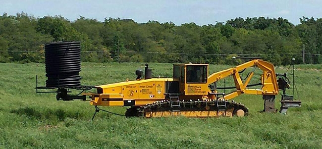 A 2050 GP model Inter-Drain double-link drainage plow was equipped with a Trimble RTK-GPS system to automatically control drain depth and grade and steer the drain plow along the drain line path for each subsurace drain planned for the field. Photos and figures courtesy of Bob Clark III. An analysis of drain depth and grade data recorded during a field installation.
This is the third paper published on the analysis of drain depth and grade data recorded during a field installation of corrugated plastic drain tubing. A 2050 GP model inter-drain double-link drainage plow was equipped with a Trimble RTK-GPS system to
automatically control drain depth and grade and steer the drain plow along the drain line path for each subsurface drain planned for the field.
A farm in Ohio was selected for the July 2016 installation of the subsurface drainage system in clay-loam soil by Clark Farm Drainage, Inc. in New Castle, IN.
The initial results analyzed and published from this field installation was to determine if the corrugated drainpipe guided down through the pipe-feeder “boot” attached behind the plow blade with a linkage system installed the drainpipe at the same depth as the bottom of the drainage channel, which was created by the cutting tip of the plow-blade.
An RTK-GPS sensor positioned directly above the plow-blade cutting tip was mounted on a cantilever arm attached to the plow-blade shank. The RTK-GPS system electronic circuit operated the plow hydraulic system to continuously adjust plowing depth to control the elevation and gradient in the bottom of the subsurface drainage channel created.
A second RTK-GPS sensor was mounted on a vertical mast directly above the rear of the pipe-feeder to detect and record the elevation of the installed drainpipe at nearly constant travel intervals during forward motion of the plow.
It was concluded that the drainpipe was continuously installed by the pipe-feeder at the same elevation as the bottom or the plowed-in drainage channel. The results of this initial analysis of the recorded elevation and grade data were presented and published in the proceedings of the American Society of Agricultural and Biological Engineers (ASABE) International Drainage Symposium, held in Minneapolis, MN on Sept. 6 to 9, 2016. (Fouss and Clark III).
The second paper was published in the November 2016 issue of Drainage Contractor magazine and provided observations and comments by drainage plow contractors about the field installation results. It also provided recommendations on additional reports to be published from further analyses of the recorded data, and suggestions for additional field installation tests. The primary observations and comments on the results published in the initial paper described the different types of pipe-feeder “boots” and the configurations of attachments or linkages for the “boot” to the plow-blade.
It was also pointed out that the differences in plow design could have a significant effect on the results and accuracy of the subsurface drainage installation, thus they recommended conducting similar field performance evaluations on other drainage plow models.
The contractors added a discussion on the need to make a comparison of the drain “as-installed” with the drain “as-designed” in the drainage system design plan, which is the focus here.
Comparing as-installed with as-designed
In this follow-up analysis and paper, the objective was to determine if the drain tubing was installed by the RTK-GPS controlled drain plow at the depth and grade specified in the drainage system design plan.
The drainage system design for the field was pre-planned with the Trimble Farm Works software, which used the topographic map data for the field site as an input.
The drain design plan specified the location via GPS coordinates for each drain line (or section line) in the data file and labeled it with identification, name, and the X, Y, Z coordinates for the downslope outlet end of the drain line.
In addition, the drain design specified the following parameters for all sections of the drain line length – minimum slope, minimum depth, maximum depth, optimum depth, optimum outlet, last data point outlet, and specs on pipe type, and pipe sizes.
These drainage design parameters were stored in a digital memory component of the RTK-GPS system prior to the installation of the drains. The RTK-GPS system is designed to automatically control the operating depth of the drain plow along the path of each drain (or section line) to “match” the drain depth and grade parameters and specifications in the design plan for that drain line.
During the drain installation, the GPS data recorded by the RTK-GPS receiver mounted on the plow-blade was considered the “as-installed” drain (this is the same digital data file many contractors have previously named drainage completed).
It was concluded in the Drainage Symposium paper that the pipe-feeder “boot” installed the drainpipe at the same elevation (or depth) and grade as recorded in the drainage completed digital file recorded by the RTK-GPS system that automatically controlled the drain plow-blade depth and grade as the drainpipe was installed.
A 2050 GP model Inter-Drain double-link drainage plow was equipped with a Trimble RTK-GPS system to automatically control drain depth and grade and steer the drain plow along the drain line path for each subsurace drain planned for the field. Photos and figures courtesy of Bob Clark III.
X-Y graphs of recorded coordinates for drain “as-designed” vs. “as-installed”
The preliminary graphs originally plotted from the field recorded data gave a close comparison of the drain “as-designed” with the drain “as-installed”, but we were not satisfied with the comparison as it was not as exact as we expected it to be. Those preliminary graphs were plotted by assuming the ground travel between coordinate data points recorded were separated by a constant travel interval – i.e., about two meters for the ground survey and drain design data, and about three meters for the drain “as-installed” data – neither assumption was correct.
The actual ground travel intervals between recorded coordinate data points varied somewhat for different plow operating conditions and perhaps ground speed. The ground surface elevation data points were recorded at 6.09 meters (20 ft.) intervals when the field topographic survey was conducted using a rover (an all-terrain vehicle mounted with a mast to record X,Y,Z coordinates) prior to developing the drain design plan or installing the drains.
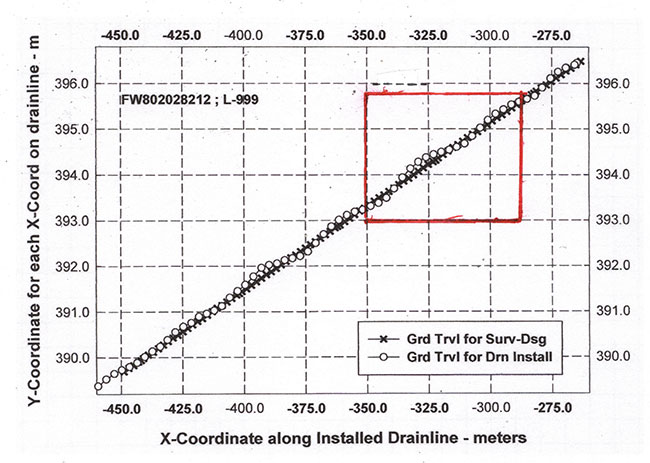
For the drain design plan created on the computer program, the data points from the survey data were used to specify the drain design elevation at each coordinate point along the drain line, and the drain line was planned as a perfectly straight line across the field. Afterward, when the drains were installed, the drain “as-installed” data points were recorded at different variable intervals (2.386 to 3.576 meters) along the drain line. Additionally, the travel path (or direction of travel) for the installed drain varied horizontally somewhat (typically less than 20 centimeters). Therefore the recorded X-Y travel coordinate data for the drain “as-installed” did not line up with the design drain line coordinate points. See Figure 1 as an example plot for one of the drain lines installed in the field.
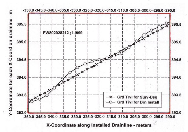
Figure 1a shows in better detail the lateral travel variation along the drain line during the drain installation for the section of the drain from X-coordinates -350.0 to -290.0 meters. This drain was installed with the drain-plow being operated at about 67 meters per minute (or 2.5 miles per hour) and automatically steered across the field controlled by an RTK-GPS sensor mounted on top of the tractor operator canopy.
The horizontal cross track error as observed in Figure 1 is not an error in GPS drift, but a matter of calibration of the auto steer system with the drain-plow. The auto steer system on this inter-drain plow works by intercepting the signal coming from the dual joystick controllers and adjusting those signals before they are sent to the hydraulic drive pumps.
To ensure the best accuracy of the steering system, the joysticks must be properly calibrated so the output signal is similar and to ensure there’s an identical signal for the drain-plow to track straight. During this drainage system evaluation installation, the drain-plow was driven at different speeds for many of the drains installed, making it difficult to keep consistent accuracy on the line when the joysticks were in different positions with each drain line installed.
With the aid of other Trimble engineers, Josh Shuler provided assistance by leveraging several Microsoft Excel linear forecasting and analysis tools to process and interpolate the recorded X, Y, Z coordinate data as the drain was installed. Several interpolation methods were used in parallel to evaluate the validity of the datasets and we found nearly all to give nearly identical results.
After the data interpolation methods and results were validated, the data was re-tabulated using the variable distance intervals between recorded data points from the as-installed data to appropriately align the datasets, rather than the previously used “approximate” constant travel interval spacing between data points. Additionally, the interpolation procedure adjusted the horizontal lateral displacement of the actual plow travel path from the straight-line drain path to the same X-Y coordinates for the ground survey data points.
In plotting the data from the re-tabulated table, the total distance traveled to any point along the drain line (section line) path was determined by summarizing the series of variable ground travel intervals for all data points to that point plotted in the drain line path.
The variable spaced “as-installed” drain elevation data points were plotted at the same variable intervals on the X-axis as the ground surface and drain design data points. This method of data processing and plotting provided a more accurate representation of reality and allowed for higher quality direct comparison and “match” between the “as-designed” elevation for the drain and the drain elevation “as-installed” at each variable interval of travel along the drain line path.
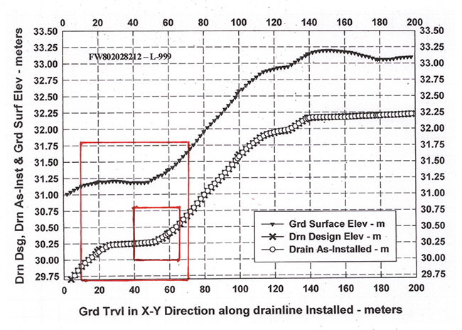
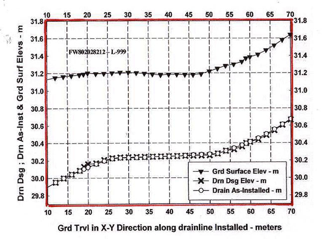
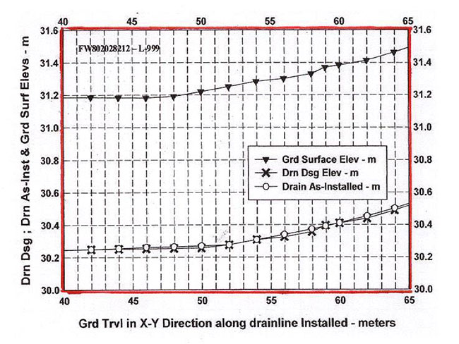
Three example graphs are presented here (Figs. 2, 2a & 2b) to illustrate that the RTK-GPS depth and grade-control system on the double-link inter-drain drainage plow did install the subsurface corrugated-wall plastic drain tubes very accurately at the design drain elevation for the entire length of the planned drain line. In the graph, the “as-installed” data points are mostly hidden behind the drain design elevation data points. Thus, as concluded in the first paper published in the ASABE International Drainage Symposium Proceedings on this RTK-GPS evaluation technology for this double-link drainage plow, the data file recorded by the plow-blade mounted RTK-GPS sensor is satisfactory for documenting the installation depth and grade for the drains and the data file can be provided to the farmer for his installed subsurface drainage system records.
To quantify the accuracy of the drain installation with the RTK-GPS controlled double-link drainage plow, the difference between the drain “installed” elevation and the “design” elevation for the drain tube was tabulated for each variable interval data point along the drain line plotted in the Fig. 2 graph. The tabulated design and installed elevation difference values were averaged, and then the standard deviation was computed for the difference at each variably spaced data point of the design elevation and the installed elevation for the drain length section shown in the graphic plot.
For drain line L-999, the average elevation difference was 0.00372 meter, meaning that the drain design elevation was on average 0.00372 meter deeper (or lower) in the soil profile than the installed drain elevation.
The standard deviation of the difference between the drain design and installed elevations was 0.0091 meter for drain line L-999. Although not illustrated here, very similar results were obtained for the analysis of installation accuracy of other drain lines installed in the field.
We recommend this type of field evaluation of drain installation quality be conducted for other drain-plow models, and giving attention to ground travel speeds and different linkage systems for the attached pipe-feeder “boot.” Further, we recommend publication of the installation accuracy evaluation results by the plow manufacturer or the contractor.
Print this page